If I had a cent for every question that I have been asked about this, I would be a wealthy Webmaster. I'm talking about the two seals between the water pump and the gearbox (See Spare Parts List - Fig. 18, Parts #30x2 (seals) and #31x2 (safety rings / circlips).
The first question is "How do I know if the seals are leaking ?". The designer of the Vire 7 thought of that problem. The manuals don't mention it, but there is an indicator hole in the gearbox housing, at the bottom of the waterpump mounting. It's on the midline of the mounting, directly above the drive shaft, so it's almost imposible to see without a mirror. The hole opens from a channel leading to the space between the outer (water) seal and the inner (oil) seal (Parts #30 in Fig. 18 of the Spare Parts Lists on the Website). If the water seal fails, water leaks into the space and out through the hole. It may give the impression that the water pump has sprung a leak. Because the water drops down onto the propellor shaft, it may even appear that the leak is coming from the propellor shaft. If the hole starts to leak, replace the seals at the earliest opportunity. If you don't, the inner seal will leak too and water will get into the gearbox, with disastrous results.
The next problem is usually access - or the lack of it. I've heard from one guy who got his friendly dentist to do the job, using mirrors. Others have been able to improve access sufficiently by removing the exhaust gas collector. But most ordinary mortals find it easier in the long run to remove the engine completely.
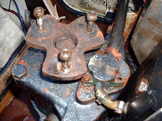
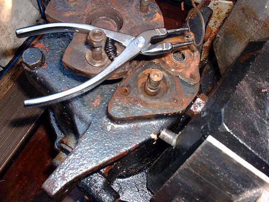
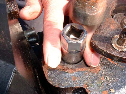
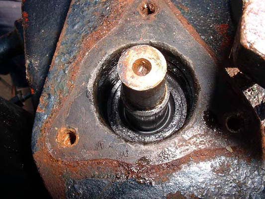
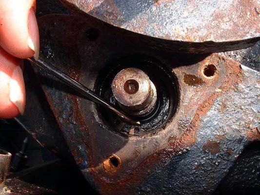
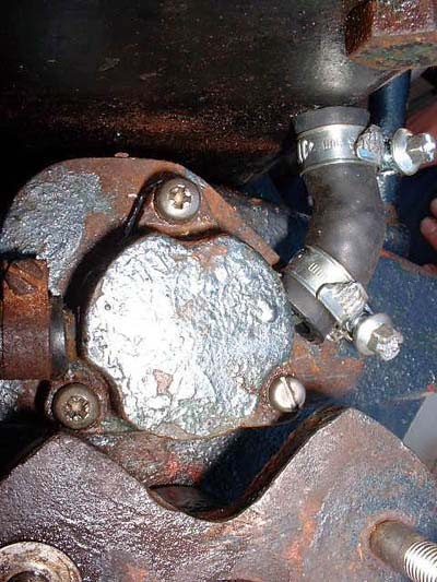
In the photo at far left the engine has been removed from the boat and stood on it's end, so that it is resting on the flywheel. The back of the exhaust gas collector is just visible to the right of the photo. The clear hose, which is slightly kinked, joins the pump to the bottom of the exhaust gas collector. In the photo, one of the bolts has already been removed or is missing. When removing the pump, take care not to lose the small Woodruff key (Spare Parts List, Fig. 18, #24) from the pump driveshaft. In the right hand photo the pump housing has been removed, as has the impellor, the backing plate (Spare Parts List, Fig. 16, #5), the outer (water) seal and both safety rings (circlips); the backing plate is still lying on the back of the gearbox beside the shaft that drives the pump (under the tip of the circlip pliers). The backing plate often stays stuck to the back of the gearbox after the water pump housing has been removed, which can be a bit confusing if you are trying to replace the seals - you can't see them. A gentle tap will usually remove the plate. Then stab the old outer water seal with a sharp screwdriver and draw it out. Also illustrated is a circlip pliers - very handy for removing the two circlips (a.k.a safety rings) that lie between the water seal and the inner oil seal. You may be able to stab the inner oil seal and pull it out too, but it's so deep that this may often be difficult. If you have trouble removing the inner seal, then drill two small holes into it and thread a couple of self-tapping screws into them. Then, by pulling on the screws, the seal can be removed fairly easily.
Now, it's time to put in the new seals. You don't have to use originals. The seal dimensions are:- outer diameter 30mm; inner diameter 15mm; thickness 7mm. With that information, any decent supplier of seals will be able to supply suitable replacements.
The outer (water) seal usually fails before the inner (oil) seal, the gearbox oil being a better lubricant than the water circulating through the pump, which may also contain some particulate matter, depending on how clean the water is where you sail. However, it's probably safest (and easiest in the long term) to replace both seals, rather than repeat the exercise in a few months time - the seals cost about 4 Euro each, so it won't break your budget (Price at August 2002).
Care must be taken not to damage the new seals or the whole operation will have been a waste of time.
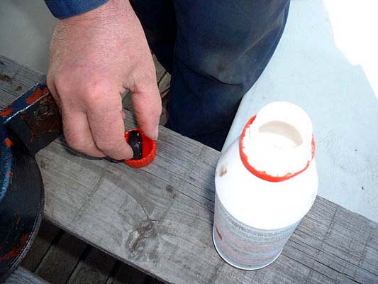
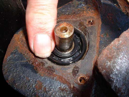
Veli-Antii, who provided these excellent photos, suggests that you lubricate the new seals with brake fluid (photo at far left). Then, sit the inner gearbox seal into place (second photo), but don't try to push it in with anything sharp, you'll just damage it. You are supposed to install the seal with the "spring" facing into the gearbox. However, here's a Tip from Chris:- "When I rebuilt the gearbox after water problems I fitted both seals at the pump part of the gearbox to keep things out. In other words the seal to keep the oil in the box was reversed. This was done as second line of defence against water entry. I did not think that there was much danger of oil leakage at this point considering that it is at the top of the box, it is behind a gear which works as a flinger and the oil is 140 SAE. Running the engine this year under a variety of conditions has confirmed this opinion". Whichever way round you face the seals, a spark plug socket is ideal for tapping the seals into place (third photo), et voilá (photo at far right).

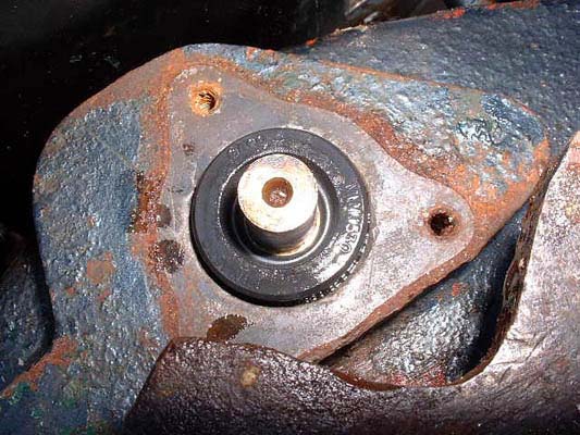
The aforementioned circlip pliers is very useful for putting the locking rings into position (photo at far left). Then, proceed as for the inner oil seal: sit the seal into place, facing the opposite way to the inner seal (second photo), and tap it into position with the spark plug socket (third photo). Then, reassemble the pump (photo at far right), taking the opportunity to replace the impellor if it appears worn. In this last photo the engine is upright again, the missing screw has been replaced, and the bit of transparent hose has been replaced with a short black hose.
31 August 2005 - Because this is a chore that you are likely to have to do again, Pete Clarke offers the followiing advice. "I've now got a quick release method tfor the water pump, designed through necessity. The 3 bolts are allen keyed and, much more importantly, the tiny pipe between the pump body and the silencer has been replaced with a large loop ( about a foot of clear pipe ) so that the pump body can come off without messing about unhooking the old pipe and reconnecting. The metal pump body output tube has to be cut back to do this but it makes the job much faster. "


